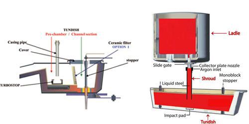
The ladle slide gate plate system consists of ladle well brick, upper nozzle, upper slide gate plate, lower slide gate plate, lower nozzle, and sliding gate mechanism, the structure of which is shown in Figure. 1.The working principle of the sliding gate plate is to make the upper and lower slide gate plate casting holes staggered through the sliding mechanism to regulate the flow of steel water.
Leakage of steel at the mating point of the upper spout and upper well block
Cause analysis
Leakage at the mud joint between the upper nozzle and the upper well block tile
(1) The leakage of steel at the mud joint between the upper nozzle and the upper well block, the mud joint is not full during the installation process of the upper nozzle or there are impurities in the fireclay, resulting in steel seepage and steel penetration in the mud joint between the well block and the upper nozzle.
(2) On the well block washout or cleaning process caused by serious damage to the surface with the mouth of the upper nozzle, washout of the upper well block openings, the upper well brick and the mouth of the sealing area to reduce or fill the fire clay is too thick resulting in larger fire clay drying contraction of the mud joints, and serious will also appear to the mouth of the upper nozzle to the ladle creeping. Steel in the static pressure gradually along the mud seam seepage steel, and ultimately lead to steel drilling accident.
(3) Longitudinal cracks in the upper nozzle, due to the poor thermal shock resistance of the upper nozzle, the pouring process of the upper nozzle inside and outside the temperature difference is large, resulting in longitudinal cracks along the length of the upper nozzle, steel along the cracks through.
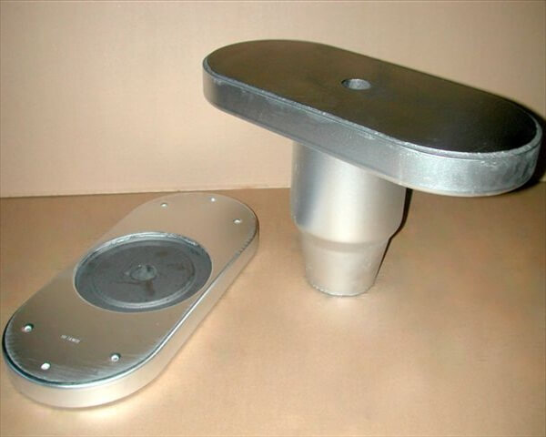
(4) Misalignment between the base of the mechanism and the mounting plate at the bottom of the bag, resulting in fracture caused by lateral stress on the upper nozzle, which is shown in Figure 2.
Improvement measures
(1) The water-cement ratio of fireclay is properly adjusted, the fireclay is soft and hard, and the fireclay must be uniformly modulated without impurities. Once the proper water-ash ratio is found, strengthen the operation specification of each team to avoid the fluctuation of fire clay caused by human reasons. And the use of barrels in the process, after use plastic film sealing cover.
(2) Improve the anti-washout performance of the upper well brick and determine a reasonable service life. When removing and replacing the upper nozzle, the wind pick strikes at a suitable angle to avoid damage to the well brick, if the damage to the inner cavity of the upper well block, the use of fire clay to repair before the installation of the upper nozzle, and the damage is serious down the line to be repaired.
(3) Improve the thermal shock resistance of the upper nozzle, install the fire clay to be uniform and full.
(4) The bottom of the package to set the well block positioning device, unpacking caused by the damage or displacement of the positioning facilities to be repaired in a timely manner. Ensure that the well block and the bottom of the agency box nozzle hole concentric.
Leaking steel between the upper nozzle and the upper slide gate plate
Cause analysis
(1) The nozzle brick creeps towards the inner cavity of the well block .Installation of the upper nozzle block, in its outer surface evenly coated with a layer of fire clay, and then squeezed into the upper spout well brick, the fire clay can not be hardened within a short period of time, the installation of the slide gate plate under the action of the spring pressure, the upper nozzle brick towards the well block cavity creep, in the process of pouring steel fire clay will be sintered contraction of steel in the steel under the action of the static pressure of the liquid steel will be along the upper well block and the upper slide gate plate between the gap between the fire clay outward seepage of steel, when the width of the steel piece and thickness When the width and thickness of the steel piece reaches a certain level, it will produce steel leakage.
(2) The sealing fire clay between the upper slide plate brick and the upper nozzle brick is too thick and too thin. In the process of pouring steel is too thick, too thin fire clay sintering shrinkage, and sintered mud layer in the presence of more air holes, especially in the aluminium-carbon fire clay carbon is oxidized, so that the fire clay strength is reduced, easy to be washed away by the steel, steel in the static pressure of the role of the steel, through the contact surface resulting in steel leakage. The steel leakage caused by the large mud gap between the upper slide plate and the upper nozzle due to the installation of the upper nozzle too deep is shown in Figure 3.
(3)The upper slide plate installation is not flat, the upper nozzle installation is high or the fire clay is hard, resulting in the upper slide plate can not be installed in place, the upper slide plate and the mechanism of the gap between the bottom box, pulling the slide plate process, the centre of gravity of the pressure in the back of the slide plate on both sides of the fulcrum formed by the back side of the back side of the move back and forth, ultimately leading to the upper slide plate and the upper nozzle mud seam cracks caused by the leakage of steel.
(4) There is no positioning device for the upper slide plate, and it only relies on the sub-mouth with 4 positioning. If the strength of the sealing fire clay is not high, the friction when the slide plate pulling the upper slide plate brick and the nozzle brick between the wrong, resulting in contact between the fire clay between the loose, the steel along the mud seam transverse through out.
(5) ladle open pouring not open, the use of oxygen tube burning eyes, burn through the refractory material leakage of steel.
Improvement measures
(1) After the installation of the upper well block, use an open fire to bake the fire clay to harden it and prevent the newly installed upper nozzle brick from creeping into the well block cavity.
(2) To prevent the fire clay too thick, too thin, strict control of the water-cement ratio of fire clay s on the nozzle installation must be standardised, on the nozzle of the sub-mouth or the mother mouth section and the agency slide box is flat or slightly lower than 2mm is appropriate. Use reasonable upper nozzle installation and positioning tools to avoid man-made operation differences.
(3) Select the appropriate fire clay, must have a certain sintering strength and resistance to steel scouring.
(4) Improve the rate of self-opening of the ladle, not self-opening the burning eye when the oxygen pipe will be bent, the oxygen pipe into the mouth of the water vertical upward push, to avoid burning to the refractory material.
Steel leakage between upper and lower slide gate plate
Cause analysis
(1) carbon-containing slide gate plate in the casting of high manganese, low carbon, low silicon steel, high concentration of oxidised substances in steel, contact with steel skateboard surface carbon is oxidised, the brick bulk density decreases at the same time as the surface strength is reduced, the steel is more likely to infiltrate the surface of the skateboard, skateboard surface was more strongly eroded, pulling the skateboard in the course of the surface of the infiltration of the steel, the gradual increase in the steel, steel slag, when the cold steel to reach a certain thickness, the skateboard between the slots occurring in the leakage of steel.
(2) pouring calcium-treated steel, steel [Ca] and aluminium-carbon slide gate plate the main component of the A1203 reaction to generate A aluminium-calcium system of low melting point compounds, low-soluble compounds by the steel scouring away, the formation of horseshoe-type erosion of the upper slide plate, the lower slide plate appears deeper and longer grooves, when the upper and lower slide plate and the length of grooves more than the slide plate safety distance, there will be the end of the pouring of steel shut off the steel leakage accidents.Figure 4 shows the higher calcium content of molten steel, the upper slide plate plate surface horseshoe erosion, Figure 4 shows the lower slide plate calcium erosion of the plate surface grooves.
(3) Serious wear and tear of the mechanism slide, track wheel and shaft, and the mechanism depressions are reduced.Spring overdue for service, spring pressure drop is large, resulting in more pressure drop between the slide plate, the pressure between the plate is lower than the static pressure of steel, the occurrence of steel leakage between the plate.
(4) Sliding gate plate surface processing precision is low, the gap between the upper and lower sliding plate more than the minimum gap between the steel penetration, plate surface gap steel in the static pressure under the action of penetration between the plates, resulting in the folder steel, with the extension of the casting time of steel penetration increased resulting in steel leakage.
Improvement measures
(1) Combined with the smelting of steel, the quality of the slide plate to improve its oxidation resistance and erosion resistance.
(2) If the calcium content in steel is high, aluminium carbon slide gate plate can not meet the use, choose magnesium carbon slide gate plate. (3) Increase institutional testing efforts, slide, small wheels, shaft wear over the specified size should be replaced in time. Regular detection of spring pressure, pressure value is lower than the specified value when replacing the new spring. The use of gas springs, each furnace should test the spring sealing, the failure of the spring to update. Ensure that the pressure between the upper and lower sliding gate plate is not lower than the design value.
(4) Improve the processing accuracy of the slide plate surface, increase the antioxidant coating on the slide gate plate surface, improve the fit between the slide gate plate.
Leakage steel between lower slide gate plate and lower nozzle
Cause analysis
Loosening of the top tightening sleeve at present, in order to improve the quality of billet, in order to prevent the secondary oxidation of molten steel during the pouring process, a long spout is installed under the lower nozzle brick. In the switch pouring process, the sliding trolley moves with the lower sliding plate brick and the lower nozzle brick, and the lower nozzle drives the long nozzle to move. After many round trips, the top tightening screw sleeve that locks the lower nozzle brick may be twisted loose, resulting in a gap between the lower sliding tile and the lower nozzle brick, causing steel leakage. Figure 6 illustrates the top tightening screw sleeve of the lower nozzle loosening and steel leaking from the mud gap between the lower nozzle and the lower slide plate.
Improvement measures
When installing the lower nozzle use a hammer to tap the top tightening swivel sleeve to lock it in place. Before sliding gate plate each time, lock the top tightening sleeve one more time.
Steel leakage caused by drilled holes or breaks in the spout
Cause analysis
(1) Refractories entrapped in low solubility impurities. Continuous casting is not self-opening using burnt-eye operation, the oxygen tube tilt angle is large on the lower nozzle aperture caused by burn damage.
(2)Fracture of lower nozzle mouth. Refractory material itself after thermal shock to form cracks. Continuous casting installation of long nozzle, robot impact on the lower nozzle, the lower nozzle fracture by external forces. Lower nozzle and long nozzle bowl with mismatch, pouring process of steel back into the gap with the formation of adhesion, the end of pouring steel pick long nozzle difficulties, push and break the damage to the lower nozzle. It is difficult to find out the internal damage of refractory material when it is used again for inspection. The nozzle breaks when it is used continuously. Figure 6 shows the leakage of steel caused by the fracture of the nozzle by external force when the long nozzle is set.
Improvement measures
(1) Refractory production environment clean up, sieve the material to avoid the material mixed into the dough.Burning eye operation will be oxygen pipe bending, oxygen pipe into the refractory nozzle when the vertical upward through the oxygen pipe, to avoid the oxygen pipe tilt angle of the refractory burns.
(2) Improve the thermal shock resistance of the lower nozzle. Design a reasonable lower nozzle and long nozzle with the form, combined with the location of the installation of sealing ring, reduce sticky steel, steel phenomenon.
The reasons for steel leakage in ladle sliding gate nozzle system are manifold, only by choosing suitable refractory materials, strengthening the maintenance of sliding gate mechanism, perfecting the standardised hot repairing operation, formulating corresponding countermeasures for the common causes of steel leakage in each part, and executing them unswervingly can the probability of steel leakage be significantly reduced.
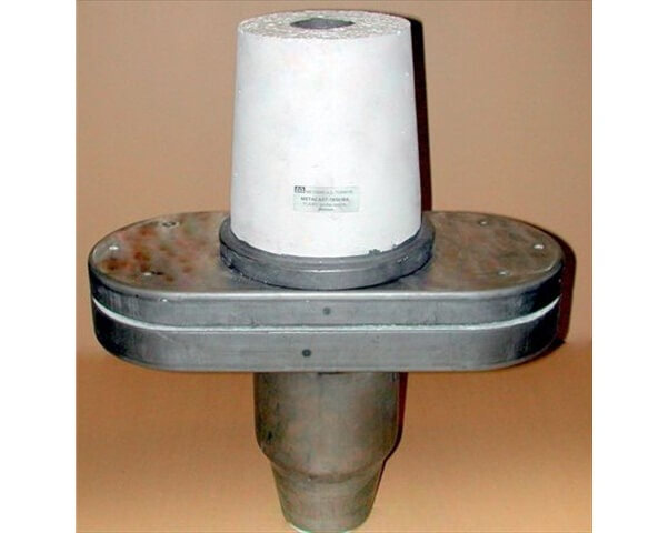
Monoblock stopper rod, also known as a monoblock stopper or simply a stopper rod, is a refractory device used in steelmaking to control the flow of molten steel from the ladle to the tundish during continuous casting processes. It is an important component in the stopper system, which regulates the steel flow and enables precise control of the casting process.
Description
Monoblock stopper rods are equipped with a control mechanism, such as a pneumatically or hydraulically operated cylinder, that allows for precise adjustment of the stopper position. This mechanism enables operators to control the steel flow according to the casting requirements. Monoblock Stopper is used mainly for flow control on Molten Steel poured from tundish to mould. Monolithic Stopper is installed in the Tundish above the Sub Entry Nozzle and the gap between stopper head and Nozzle decide the throughput requirement of Molten Steel inside the Mould. Mono-Block Stoppers in conjunction with Sub Entry Nozzle or Tundish Nozzle allow the Metering of flow of Steel in mould thereby allowing only desired flow in mould . This requirement necessitates many types of configuration on Stopper head and many types on Sen Cup combination of which deliver the optimized results for flow .
Monoblock Stopper Advantages:
Monoblock stopper rods are available in various sizes to accommodate different ladle and tundish designs. They can also be customized to meet specific requirements, such as flow capacity, refractory material composition, or control mechanism preferences.
1.Anti-erosion: Advanced material formulation to effectively resist the physicochemical effects of the melt. 2.Antioxidant: Advanced anti-oxidation mechanism to ensure good protection of graphite in products. 3.High temperature resistance: use temperature 1770°C4.High strength: high quality materials, high pressure pressing, reasonable combination, high temperature strength, scientific product and high anti-scouring ability. 5.Less pollution: The material is designed with the relationship to the metal being smelted and the process characteristics,without any harmful impurities. 6.Long service life: ductile iron casting life is generally not less than 48 hours, gray iron casting is generally not less than 72 hours.
Monoblock Stopper Function
1.Control the steel flow from tundish to mold. 2.In conjunction with a slide gate as an shut off device and to prevent slag vortexing at low tundish level. 3.To introduce argon into the pouring channel to prevent build up of clogging materials.
Preheating institiution of stopper and intermediate ladle before anguss Room temperature 1.900°C and heating-up time:20mins.
2.900-1150°C and heating-up time:20mins. 1150°C ,2.5h holding temperature and then start pouring.More information please visit HYRE
Ajang kompetisi bergengsi, MM CUP 2025, telah resmi ditutup. Acara yang berlangsung sengit dan penuh antusiasme ini telah berhasil menobatkan para talenta terbaik sebagai juara di kategori Putra dan Putri. Setelah melalui serangkaian pertandingan yang ketat, berikut adalah daftar tim yang berhasil meraih podium di MM CUP 2025.
During the continuous casting operation of the continuous casting machine, the stable use of the ladle long nozzle, the tundish stopper rod and the immersed nozzle is the key to achieving high-reliability continuous casting. The use of the tundish stopper rod mainly causes the adhesion of inclusions and the erosion of the stopper rod head. The slag-making process optimization and calcium treatment can effectively solve the problem of inclusion adhesion. Therefore, the stopper rod erosion problem has become the key to affecting the stable continuous casting operation.
Analysis of the Causes of Stopper Rod Erosion
Stopper rod material and production steel type
All stopper rods currently in use are made of aluminum carbon (Al2O3-C). When producing low-silicon aluminum killed steel, slag line erosion is prone to occur. In particular, when producing low-carbon, low-silicon aluminum killed steels such as ML08Al and XGM6-1 with a finished carbon content of less than 0.10%, the slag line erosion phenomenon occurs frequently. In severe cases, the slag line erosion rate of the stopper rod can reach 80%, and the stopper rod breaks at the slag line, causing production interruption.
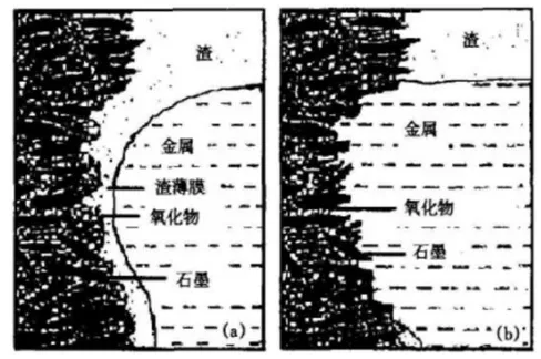
Erosion reaction mechanism of slag line
The Marangoni effect plays an important role in the local erosion of refractory materials at the steel-slag interface. In the actual production process, the slag line of carbon-containing refractory materials causes the slag-steel interface to fluctuate due to the interfacial tension, resulting in local erosion of the slag line material, as shown in the figure. Since the stopper rod is in a continuous up and down reciprocating motion in the tundish, the erosion of the slag line will be further aggravated.
In the tundish, in order to avoid direct contact between molten steel and air and prevent secondary oxidation of molten steel, a covering agent is added to the surface of the molten steel for protection. At this time, a temperature gradient is generated in the tundish, causing convection between molten steel and slag at the slag line, increasing the scouring of the slag line of the stopper rod. This micro-circulation caused by convection at the slag-steel interface will aggravate the erosion of the refractory.
Molten steel erosion of stopper rod
When producing low-carbon, low-silicon aluminum-killed steel with a carbon content of less than 0.10% in molten steel, aluminum is used for deoxidation and killing. The molten steel will be treated with calcium before being cast. At this time, the carbon in the stopper rod will be immersed in the molten steel to form a decarburized layer. At the same time, the calcium treatment of the molten steel will cause a significant increase in CaO in the molten steel. In addition to the denaturation of Al2O3 in the molten steel, excessive [Ca] and [CaO] will react with Al2O3 in the stopper rod matrix to form a large amount of low-melting calcium aluminates such as 12CaO·7Al2O3 and CaO·Al2O3, which will flow into the molten steel and slag to form corrosion.
In the actual production process, when the Al content of molten steel is controlled at 0.045% and the calcium content is controlled at 0.010%, corrosion still occurs. Through on-site tracking research, it is found that the main reason for the corrosion of the slag line at this time is that the CaO component in the slag layer in the tundish pouring area reacts with the Al2O3 in the stopper rod matrix to produce the same corrosion condition.
Effect of Tundish Temperature on Slag Line Erosion
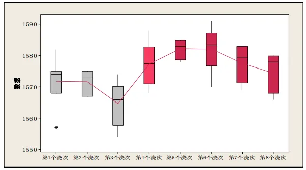
The slag line erosion problem of XGM6-1 ultra-low carbon steel stopper rod is the most serious. The corresponding relationship between the tundish temperature and the slag line erosion is statistically analyzed. As shown in the figure, the average tundish temperature of the first three pourings was controlled at 1567-1575℃, the slag erosion of the stopper rod was relatively light, and no erosion fracture occurred. The average tundish temperature of the last five pourings in the figure was controlled at 1577-1583℃, and the stopper rod erosion fracture occurred.
Improvement measures
Strictly control the slag discharge of large bags
The main sources of slag components in the middle ladle pouring area are ladle refining slag, middle ladle covering agent and molten steel inclusions floating up and melting into the slag layer. Among them, the low-silicon aluminum killed steel refining slag with more serious stopper rod erosion is a high-basicity refining slag system, and the CaO content in the slag is controlled at 55%-65%. The slag of each furnace’s large ladle will form refined slag enrichment in the middle ladle pouring point area. During the transfer process and when the steel flow hits the slag surface in the pouring point area, the refined slag will enter the pouring area and erode the stopper rod.
Therefore, it is necessary to strictly control the slag of the large ladle, and use automatic control of slag detection to avoid a large amount of slag at the end of pouring. At the same time, the slag discharge operation of the middle ladle should be adopted. When the large ladle continuously pours 5-7 furnaces of molten steel, the slag discharge operation of the middle ladle is carried out to raise the liquid level of the middle ladle to control the thickness of the slag layer in the pouring point area.
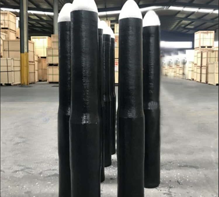
Ladle Shroud, also named as ceramic pipe, is used as a connection pipe between Ladle and Tundish. In order to keep the molten liquid from being oxidized and splattered when it flows from Ladle to Tundish, it is needed to be installed underneath the Ladle.
We also carry out Total Tundish Management (TTM) it is required to supply all the items involved in a Tundish, including technical services and applications at site.
The ladle shroud nozzle for continuous casting is also called the protective sleeve. It is an important component connecting the ladle and the tundish. It is connected to the lower shroud of the sliding shroud device at the bottom of the ladle, and the lower end extends into the tundish.
The shroud is an important functional refractory material for maintaining casting and improving steel quality. The length of the shroud is generally 600-1800mm, the pipe diameter is 90-150 mm, and the structure of the ladle shroud nozzle is shown in Figure 2. Its use conditions are harsh and must have the following functions: excellent thermal shock resistance; good mechanical strength; excellent resistance to alternating corrosion of molten steel and slag, high oxidation resistance, and in addition, other suitable properties are required for some special steel grades.more information,please check here
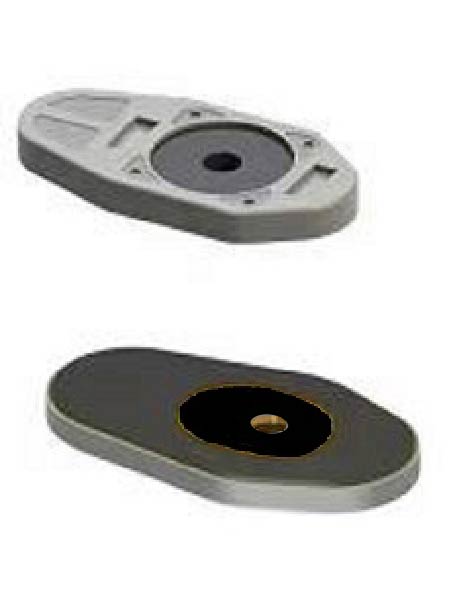
Slide Gate Plate is a critical component in the continuous casting process, used to control the flow of molten steel from the ladle or tundish to the crystallizer. The following is a detailed description:
Role and Function
Flow Control:The sliding gate plate adjusts the opening size of the nozzle through the sliding mechanism, thereby controlling the flow of molten steel. This is very important for maintaining a constant and controllable casting process.
Operational Flexibility:The sliding gate plate allows operators to adjust the molten steel flow rate as needed during the casting process to adapt to different production requirements and conditions.
Emergency Stop:In an emergency, the sliding gate plate can completely close the flow channel and stop the flow of molten steel, thereby preventing accidents and losses.
Slide gate plate for Converter The slide gate plate is made of sintered corundum, fused corundum, fused zirconium corundum, zirconium mullite and other main raw materials. It is combined with new resin, formed by high pressure and fired at high temperature. It has the advantages of high strength, super hard, high temperature resistance and corrosion resistance, and strong thermal stability.
Monoblock Stopper is used mainly for flow control on Molten Steel poured from tundish to mould. Monolithic Stopper is installed in the Tundish above the Sub Entry Nozzle and the gap between stopper head and Nozzle decide the throughput requirement of Molten Steel inside the Mould.
Argon can be blown into the tundish through argon inlet to prevent nozzle from Clogging ( specially designed feature wherever it is required we design and customise accordingly)
SPECIAL FEATURES: o Facility for gas purging o Anti oxidant properties o Design and size as per customer’s requirement o Clogging free casting for long sequence of casting o Gas purging facilities to prevent alumina clogging (optional) o Slag zone immersed part re-inforcement with special material for long life o Argon sealing purging arrangement can be provided on customer’s request o Wide range of formulation for withstanding oxidation and long sequence casting o Different assembly methods for assured security even in long sequence casting o We manufacture Silica free Oxy-bore ladle shroud for less corrosion and long sequence casting
Monoblock Stopper is used mainly for flow control on Molten Steel poured from tundish to mould. Monolithic Stopper is installed in the Tundish above the Sub Entry Nozzleand the gap between stopper head and Nozzle decide the throughput requirement of Molten Steel inside the Mould.
Argon can be blown into the tundish through argon inlet to prevent nozzle from Clogging ( specially designed feature wherever it is required we design and customise accordingly)
sequence casting o Different assembly methods for assured security even in long sequence casting o We manufacture Silica free Oxy-bore ladle shroud for less corrosion and long sequence casting